Prolonging Power and Efficiency:
Optimizing MOSFET Switching Frequency in BLDC Motor Control
In the realm of electric vehicles (EVs) and beyond, MOSFETs play a pivotal role in controlling BLDC motors, determining both performance and longevity. The lifespan of MOSFETs, crucial for efficient motor control, is directly influenced by factors such as switching frequency, power dissipation, current and voltage ratings, switching losses, and dead time. In this blog, we explore strategies to optimize MOSFET switching frequency, enhancing the overall durability and reliability of your EV’s motor control system.

MOSFET Capacitance: Enhancing Switching Efficiency
MOSFETs exhibit inherent capacitance between the gate and source terminals, impacting their ability to switch at high frequencies. Optimal performance requires MOSFETs with low gate-source capacitance (CGS). Choosing components with reduced CGS facilitates higher switching frequencies, contributing to increased efficiency and extended lifespan.
Power Dissipation: Managing Heat for Longevity
Switching at high frequencies generates significant power dissipation in MOSFETs, leading to overheating and potential failure. Effective heat management is critical, emphasizing the selection of MOSFETs with low on-resistance (RDS(on)). A well-designed circuit with minimized power dissipation ensures sustained performance and durability.

Current & Voltage Ratings: Ensuring Compatibility
Sufficient MOSFET current and voltage ratings are imperative for the specific motor and application. The chosen MOSFET must handle the maximum current drawn by the motor and withstand the highest voltage it will experience. Aligning these ratings with your motor’s requirements safeguards against premature failure.
Switching Losses: Minimizing Energy Dissipation
Switching losses occur during MOSFET ON & OFF transitions, dissipating energy as heat. To prevent overheating and failure, opt for MOSFETs with low switching losses. Additionally, circuit design optimization reduces overall switching losses, preserving the integrity of MOSFETs and enhancing the robustness of the motor control system.

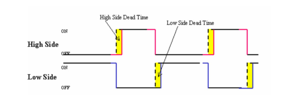
Dead Time: Mitigating Shoot-Through Risks
Properly designed dead time, the interval between turning off one MOSFET and turning on the other in a half-bridge circuit, is crucial to prevent shoot-through current that can damage MOSFETs. Careful consideration of dead time in your design not only safeguards against potential damage but also contributes to overall system efficiency.
Formulas for Optimizing Switching Frequency:
- MOSFET Gate Charge: Qg = Vgs x Cgs, where Vgs is the gate-source voltage, and Cgs is the gate-source capacitance.
- Turn-Off Time: toff = Rg x Coss, where Rg is the gate resistance, and Coss is the output capacitance.
By leveraging these factors and formulas to optimize MOSFET switching frequency, your EV’s motor control system stands to benefit from increased efficiency and extended lifespan. Whether you’re powering EVs, LED lighting, or other electronic devices, our MOSFET solutions are engineered for durability and performance.
Contact us today to explore how our advanced MCU technology can elevate your motor control applications to new heights.

